The technical details compiled and reported here are to be attributed solely to the author of this website.
What follows is meant only to illustrate a 'possible' use of hydro power at Malibu, and is typical of the other
systems presented on this web site. The photos are true, as are the basic facts, but no reference is implied to
the actual work being done by the contractors.
This page updated February 20, 2004. ; See the photos page for the latest pictures.
|
Topics covered (Each
sections ends with a return to "Topics" button.)
There are lots of photos in this file, so it may take some time to load, be patient, the
pictures are very informative.
|

|
|
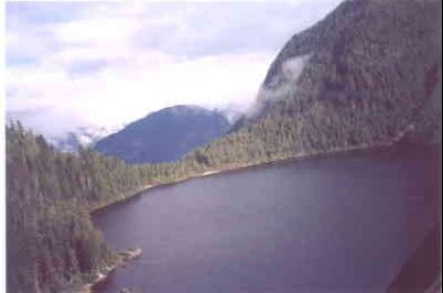
The entire short length of McCannel Creek, falling from the lake at 2650 feet to the tide line. The proposed intake will be just above the highest logging slash not far down from the lake. This is at the 2200 foot level. A detailed survey is planned for Oct 25 2001 to obtain photographs and exact elevations.
The penstock will run down through the forest to the right of the creek in the photo. About half the route is through heavy timber that was selectively hand logged about 80 years ago.
The power house will be located 250 feet from high tide line, close to where there is an obvious change in direction of the beach, toward the left of the photo.
BC Air photo 30BCB99035 No. 193
Higher resolution copies of this picture showing a larger area including a color print are available at the bottom of this web page, they are larger files of 100 to 200 kilo bytes in size.
|
Site Access and Roads:
Access to intake and along penstock:
|
|
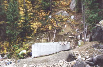
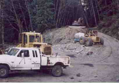
The staging area was cleared out on the site of an old logging camp. The area provides room to
unload and stack the many lengths of steel pipe. It will also serve as a landing area for the
helicopter which will be used to haul concrete up to the weir at the outlet of McCannel Lake.
The underwater cable will come ashore a 300 meters to the south nearer the outlet of the creek.
|
|
Just before the route was cleared.
|
|
View up the line of the penstock.
|
|
Top end of road.
|
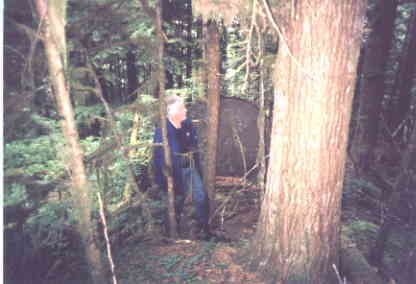
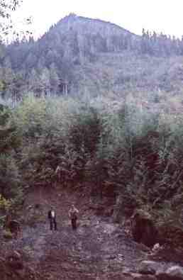
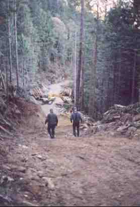
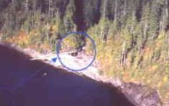
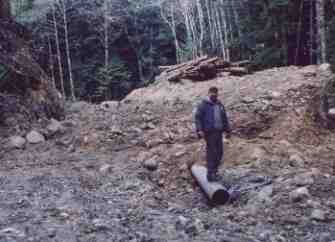
Shown below are three views of the penstock route. The two figures are at the base of the so
called 'shoot', the prominant feature which runs up to the top left of the logging slash on this photo. This is the line of the penstock, and in this view, a cat has made the first cut at the hill. See the last photo on this page for a closeup.
A few weeks later, the route had been largly cleared and high spots blasted out of the way.
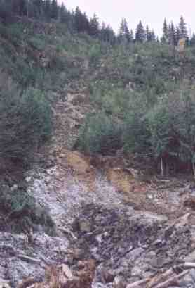
The second shot shows the mid part of the hill, just below the steepest section. Pipe now
reaches the top of the slash, and was winched into place using 1.25 inch wire cable, large
double wheel blocks, and a D8 Cat.
Higher up, the road reaches right to the creek at the 1200 foot level. The third photo is taken
standing on the creek bank looking down to across the hill towards the top of the 'shoot'
section. Lighter weight 12 inch steel pipe will be burried along the road here. It will be
joined using mechanical couplings rather than by welding.
|
 |
|
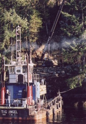
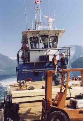
The 'Tag Angel', a twin engine landing barge used to transport all the pipe and machinery
for the project.
This barge can deliver larg equipment right to the beach, and has a long ramp for off loading. Pictured on
the left is a crane lifting pipe off deck, and on the right is a load of lumber on its way to Malibu.
|
|
 |
Typical Mountain side slopes:
Details of the slope by McCannel Creek:
Dense slash obliterates much of the lower slopes. During the US work week in March 2002 we built a rough trail which gives easy access to the forest above. In the forest, travel is quite easy up to 1800 feet, and just requires flagging.
This is it! A trail clearing crew heads
out to start the work. |
|
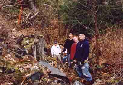
Clearing trail through logging slash.
. |
|
Photos from initial survey in July 2001 up to 1500 feet on McCannel Creek.
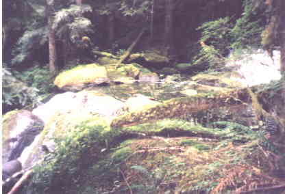
We encountered some exposed rock outcrops and low cliffs in the forest. No loose rock was observed on the hike up to 1550 feet. McCannel Creek flows over many falls and the rock looks for the most part to be solid. (Granitic, part of the coast crystalline complex.)
|

BC Air photo 78112 #213 July 1978 |
|

BC Air photo 78112 #239, July 1978 |
|
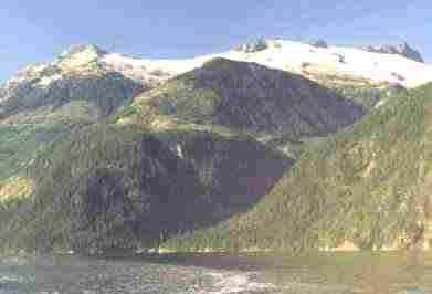
The high ridge, Sept 2 1990 |
|
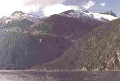
The high ridge, August 30, 1995 |
|
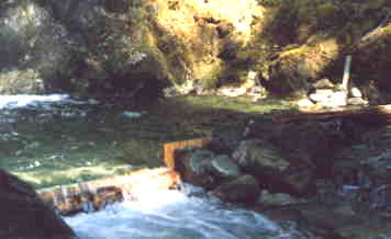
The weir we built on August 19, 1990. The
weir was washed away later in the season. |
|
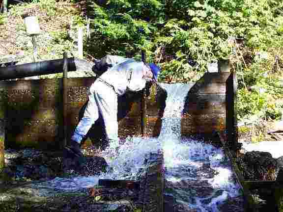
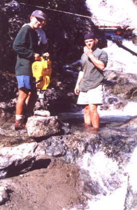
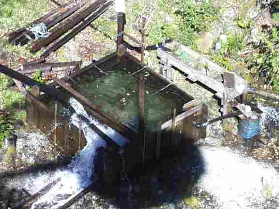
The filter box and rectangular weir showing
a flow of 2.8 cfs on August 29 1994.
|
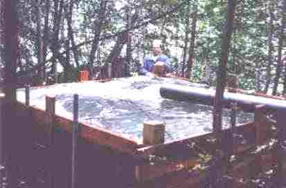
Later in 1994 when we built the large settling tank on the road we cut a "V"
notch weir in the tank so we could get a very accurate reading of the flow. This could be
read off a gauge by the person in charge of cleaning the filters.
In the spring of 1999 we installed a radio equipped water level sensor which would relay
the water level to camp every 4 hours. Its principle use has been to warn of excessively
low water levels and sound an alarm if the level dropped by 50 %. No daily records have
been kept so far.
|
| 
|
|
The "V" notch weir we built into the side of the filter box. This improved weir is able to handle up to 5 CFS, or 142 liters/sec which equates to 300 kW of net power at camp. This shot shows Dave Wheeler checking the flow on Sept 15, 2000. The flow is 10 inches deep through the weir, or about 1.6 cfs. Although the river has more water in it than this, the pipes are arranged to keep the flow below the maximum available to prevent erosion.
The flow in McCannel Creek is much higher than this, and requires a weir able to pass much more water. We did not place a weir on Helena creek as planned, so there is no data to compare the creeks volume throughout the year.
|
|
V notch weir table, for Helena Creek.
Weir tables provide a quick and accurate means to determine water flow by
measuring water depth flowing through a calibrated notch. The following table
shows depth in inches and flow in cubic feet per second and in liters per second.
The approximate energy in kW available for camp use is listed at the bottom.
This assumes a net head as indicated in feet, and an overall efficiency of 60%. Pipe losses are included in the 60% figure. The net head is the same as the gross head in these calculations, and may be less depending on pipe line length and diameter.
| Depth / inch |
4 |
5 |
6 |
7 |
8 |
9 |
10 |
11 |
12 |
13 |
14 |
15 |
16 |
| Flow / cfs |
0.16 |
0.28 |
0.44 |
0.65 |
0.91 |
1.22 |
1.58 |
2.01 |
2.50 |
3.05 |
3.67 |
4.37 |
5.13 |
| Flow / l/s |
4.53 |
7.93 |
12.4 |
18.4 |
25.8 |
34.5 |
44.7 |
56.9 |
70.8 |
86.3 |
104 |
124 |
145 |
| Net kW @ 1250' |
10.2 |
17.9 |
28.2 |
41.6 |
57 |
77 |
100 |
127 |
158 |
193 |
233 |
277 |
328 |
Four foot wide horizontal notch weir table, for McCannel Creek.
| Depth / inch |
1 |
2 |
3 |
4 |
5 |
6 |
7 |
8 |
9 |
10 |
11 |
12 |
13 |
| Flow / cfs |
0.3 |
0.9 |
1.6 |
2.5 |
3.5 |
4.6 |
5.7 |
7.0 |
8.3 |
9.7 |
|
|
|
| Flow / l/s |
8.5 |
25.5 |
45.3 |
70.8 |
99.1 |
130 |
161 |
198 |
235 |
275 |
|
|
|
| Net kW @ 1500' |
22 |
69 |
122 |
190 |
267 |
350 |
434 |
533 |
633 |
740 |
|
|
|
| Net kW @ 2200' |
33 |
100 |
179 |
280 |
391 |
541 |
638 |
783 |
928 |
1085 |
|
|
|
|
| 
|
|
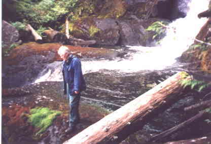
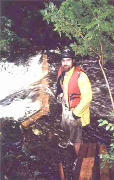
McCannel Creek and the fantastic weir Mike Schroder built in August 2001. This shot shows the river flowing at
a flood level. Typically the weir will have between 6 and 12 inches of water in the notch.
This will provide from 400 to 700 kW of energy depending on system design.
| |
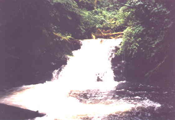
McCannel Creek at flood levels, August 18 2001. The advantage to using McCannel Creek is the large lake
at the source. We have over one million square meters of lake area, and a larger catchment basin than on
Helena creek. We will be utilizing the lake as a natural reservoir to draw upon at times of peak electrical
demand. This involves building a small weir to maintain the lake at its high water point for longer into the season.
|
(Back to top)
Water Intake, lake weir and river weir:
McCannel Lake fills a large glacial cirqe and is filled from melting snow and run off. Throughout the year the lake level varies by up to 6 feet.
This is due to heavy in-filling with the only outlet being a narrow slot through which a limited amount of water can pass.
Following the rain, or in reduced times of melt, the lake level begins to drop. After a dry summer like 2003, the level can
be so low that very little passes through this slot, and the creek is maintained only by water leaking underground.
A small weir, or low dam, will be placed at the lake outlet to aid in maintaining the water at a higher level by limiting the discharge into the creek.
The weir will have a large pipe and valve in its base to pass the minimum required 2 cubic feet per
second required to maintain the creek. This is in addition to the water which will be spilled to create power.
Water regulated at the lake will flow down the creek from the 2,300 foot level to the 1,200 foot level. Here a
second weir across the creek will form a large deep pool from which the 12 inch penstock will draw water at a
rate of up to 7 cfs.
|
|
The creek from the lake to sea. |
| |
|
Air photos of McCannel lake. Photo at right showes area of small weir.

McCannel Lake, frozen energy. | |
We hiked up to the lake in spring and
it was still frozen. Open water near the outlet was visible, but the snow was still about 6 feet deep everywhere
else! This is where the low weir will be constructed across the lake outlet. Photo above, area circled.
In summer, no snow is visible anywhere in this valley. The surrounding hills are about half exposed rock and half treed.
The vegatation cover is minimal at higher elevations, so rain very quickly runs off which is why the creek floods so quickly.
|
Intake Works
The most critical part of any hydro site is the point where water is first taken from
the stream. High run off and debris laden torrents can wipe out even the strongest
structure. For this reason, intakes that take advantage of the natural bedrock are often
desired. Working with the solid rock of the stream bed provides the strongest structure.
On the Helena Creek intake, (which supplies a smaller hydro and Malibu's water) we cemented a steel pipe into the
natural bed of the river. With some minor drilling and blasting, we were able to draw off
sufficient water with minimal concrete surrounding the pipe in the river bed.
Protection from the ravages of high flow was gained by placing the intake in the lee of a
dome of bedrock. Most flow is naturally diverted around the dome, and any fast moving
boulders are flung over the intake. Another key element of this design is that the pipe
nearest the river is easily replaceable in the event of loss.
These are photos of work we did on Helena Creek in 1993 in preparation for building a 200 kW
hydro plant back then. The current project is being built across the inlet on McCannel Creek, but as these
pictures are typical of (smaller) intakes, they are are good examples. (This has been a long campaign!) See
the 'Photos' page for recent pictures on McCannel Creek.
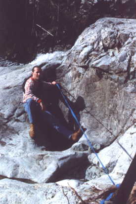
The pipe now follows the blue
tape line.
|
|
Drilling the intake in the river bed.
Drill is gas powered. |
|
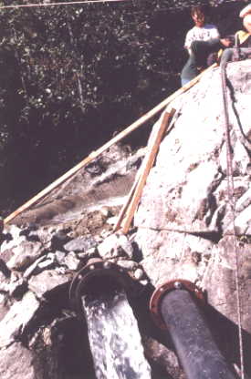
A 10 inch steel pipe cemented
in place, plastic pipe connects to it. |
Forming the intake in Helena Creek, 1993.
|
|
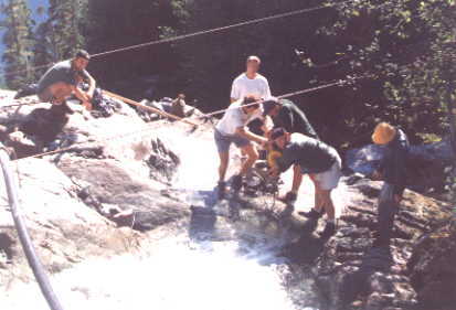
Frank Porier supervising the diversion channel being formed. This work was done
at the end of August following
a dry summer to take advantage of the low water level. The majority of the flow was
diverted with sand bags.
This intake is as good ten years later as the day it was made, but the connecting
pipe shows evidance of significant bashing by rocks carried in flood conditions.
In the spring of 2003 a major slide came down a side channel just above our present intake. It left a great pile
of logs and debris just below the intake.
|
|
|
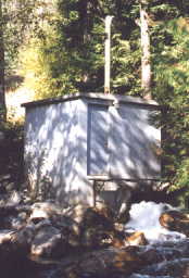
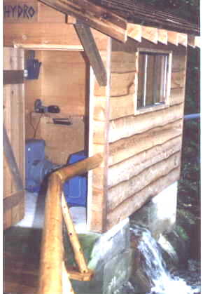
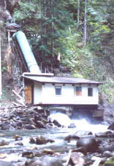
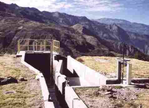
Settling and filter box:
Once the water has been drawn from the creek it must be filtered to prevent any debris from entering the penstock. Even sand can have a destructive effect on the turbine runner. A stone would be devastating, and could plug the jets resulting in a sudden stopping of the flow and possible rupturing of the piping. Pictured here is a large box we built on the logging road at Helena Creek. We use it to settle out debris and also to provide a means to get accurate flow measurements. The McCannel site will use the pond formed in the creek as a settling basin.
This is not the ideal shape or design for such a settling tank, but given the fact that all the lumber, cables and pipe was carried up a four mile road to 1500 feet by a spring work camp, it was an excellent accomplishment. The box has been in operation for about 10 years to date and is used to filter the irrigation water used at the camp. It is also the source for the water for the newly revised 12 kW hydro plant mentioned later in this web site.
John Kautz checking flow. |
|
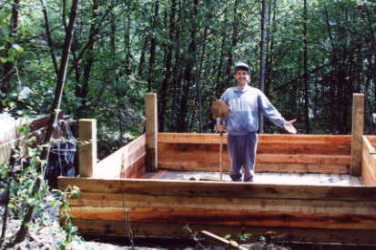
Ron Kinders, proud builder. |
|
The box from a helicopter. |
Dave Wheeler tests water. |
|

Drawing of design. |
|
A well designed settling tank. |
The photo on the right is of a properly designed settling tank, often called a forbay tank. A 2 mile long flume brings water from the intake to here. Sand settles out and can be flushed through a separate drain. The penstock leaves the tank at the far end, several feet off the bottom, but deep enough so it does not suck any air. It is a good idea to equip such tanks with water level detectors to warn the operator it the tank level drops below normal.
This was not the case in this photo, taken in Peru, and during initial testing the water level began to drop in the penstock. The RPM remained the same but the power output fell off quickly as the load manager shed loads. Finally the system shut off from under-speed.
(Back to top)
Penstock: (pipeline)
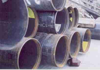
Ready to go! pipe on the dock at
Egmont ready to load on the barge. |
|
Steel pipe is going to be used exclusively on this project. The upper section will be approximately 0.25
inch wall, 12 inch diameter pipe in 40 foot sections. It will be joined with Victaulic? mechanical bolt together
fittings. The pipe will be burried along the access road as much as possible.
At the 900 foot level, the pipe will change to heavier wall, and be welded together. Expansion joints will be
included as necessary to reduce the stresses imposed by temperature changes.
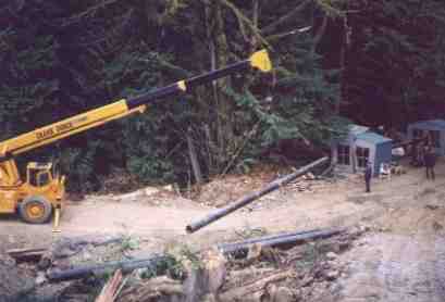
|
| Lifting one ton sections of pipe into place for welding. |
|
 |
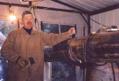
| |
The two welders are kept warm and dry in small huts seperated by one pipe length and build over
the pipe line. When the sections are joined, a machine pulls the long section, up to 500 feet long, just 40 feet
so the next stick can be attached.
They are able to complete over 300 feet of pipe in this way in one day. |
| |
The bottom end of the penstock, with over 3000 feet now connected and burried. Once the penstock is completed,
the bottom end will be seccured to a thrust block and a section will be fitted to connnect to the main valve before
entering the turbine.
A communications cable follows the pipe all the way to the top. This will be used for a 4-20 mA current loope to monitor
the water level in the pool behind the weir in the creek.
|
Should the creek discharge fall below the turbines requirements,
a probe in the pool will signal the turbine to throttle back on the water passing through the nozzle. This will cause
the output to drop, and it will be up to electronic load managers to ensure that sufficient power is still available
for basic needs.
Penstock Anchors:
Concrete anchors will have to be placed at all thrust points.
Supporting the pipe:
Cribbing and concrete supporting structures hold the pipe. It is unlikely that this penstock could be buried.
Spanning uneven ground:
As above.
Bends:
Wherever there is a bend in a pressure pipeline, there are two or more thrust vectors to counter. Concrete blocks are generally built around the pipe to provide support. By far the largest load will be the weight of the penstock pulling down the hill. The availability of bedrock to tie the anchors into is important.
Flows:
Water flows down the pipe at a slow rate of speed, typically 5 feet per second. The
pressure steadily increases in proportion to the increasing drop. It is the high pressure
that forces the water out the nozzle. The actual rate of flow in the penstock is
relatively unimportant, unless the pipe is so long that is adds too much friction to the
flowing water.
 |
|
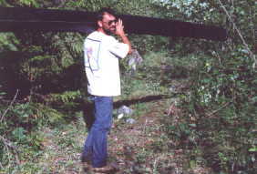
Pictured is John Smosuik(?) carrying a 20 foot length of 10 inch plastic pipe
up to the Helena Creek intake. We
have carried lengths up to 40 feet to the intake works at the 1450 foot level. This
generally takes a small crew, as the pipe is stiff and awkward to carry up the road. John
carried this piece all the way to the top, stopping only for a smoke and a coke! |
|
 |
|
In 1995 we began work on the Helena intake. As mentioned under the section on intakes, we
placed a section of 10 inch steel pipe in the river. This has a large flange welded on, and
permits us to bolt on a 200 foot section of HDPE which runs to the filter box. This really works well, and has survived the heavy spring floods. |
|
 |
|
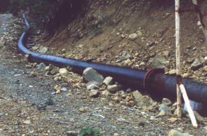
This shows and example of 12 inch HDPE pipe laying on an old road. Shown behind the
white pole is the join where the plastic pipe is replaced by 12 inch steel pipe. This is
done to accommodate the increasing pressure. On McCannel, we would use several sizes of pipe to suit the increasing pressure. |
|
 |
|
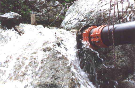
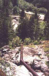
A functioning 12 inch diameter penstock. This steel pipe is supported off a solid rock
base and is held in place by steel pins drilled into the rock. Cables and turnbuckles are
attached to steel tabs welded to the pipe wall. |
(Back to top)
Turbines and Generators:
 |
|
There are two main classifications of water turbines in use. Turbines that operate under conditions of high volume and low head are known as reaction turbines. Typically these are the units installed in large hydro electric dams, generating hundreds of mega watts. Reaction turbines rely on the actual weight of water flowing past the blades. It is the high torque rather than the speed which is important. Such turbines types include the Francis, Propeller, and Kaplen runners.
The other main classification is the impulse turbine. These operate under conditions of lower flow but much higher pressure. It is the actual jet velocity striking the blades that imparts the kinetic energy of the flowing water to the spinning turbine. Impulse turbines include the well known Pelton Wheel, the Turgo, and the Cross Flow.
In all cases, turbine design has become a very exact science, the goal of which is to extract the maximum energy from the water resource. Even a one percent increase in efficiency will represent an enormous amount of power over the life of a generating plant. The same holds true for a diesel power plant.
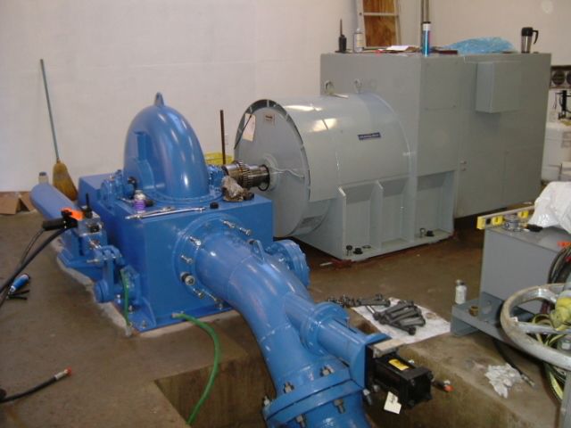
Shown here are two examples of pelton turbines which operate continuously under relatively high heads. The first is producing 120 kW under 650 feet of head, and the second is 40 kW under 300 feet of head.
|
|
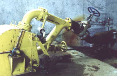
Detail of spear valve used on impulse turbine pictured to right. This runner was manufactured by Dependable Turbines of Port Moody B.C. www.dtlhydro.com
Much of the equipment on this web site was manufactured by this company, including the two turbines pictured above as well as the 12 kW plant Malibu built in 1993 as a demonstration project. See the section on "Winter Hydro" for the full story.
|
|
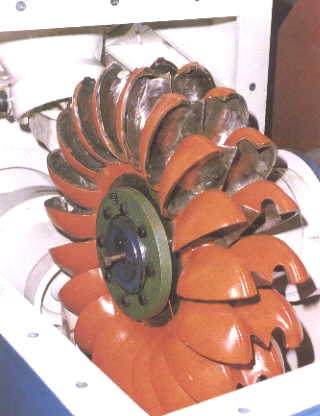 A massive multi nozzle pelton wheel capable of many hundreds of kilo watts. These units are cast from stainless steel, have heavy shafts and bearings, and a life span of decades. A massive multi nozzle pelton wheel capable of many hundreds of kilo watts. These units are cast from stainless steel, have heavy shafts and bearings, and a life span of decades. |
(Back to top)
|
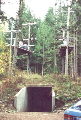
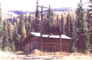
Power line and transformers:
An under water power line consisting of three parallel conductors. Transformers at the hydro generator will raise the generator voltage from 600 to 15,000. Transmission voltage will be at 15,000 volts. Another transformer at camp will step the line voltage down to 120 and 208 volts for use at camp.
The underwater survey has just been completed. (Oct 20, 2001) Results look good for the prospect of laying the cable directly on the bottom of the 1000 foot deep inlet.
Interface and Switching at Malibu:
Tying the hydro into the existing grid will be done in the power house at camp. It is likely that an additional small building will be required for the transformers and main breakers.
Power house upgrades will be required to handle the additional circuits feeding power to the new buildings. Much of this energy will go to provide heating in the cool season, when Malibu opens in March. The gym is already plumbed for hydronic (hot water) heating.
It is unlikely that the hydro and diesel would ever have to be run at the same time. McCannel creek has sufficient water to handle all the camps power needs based on this past summers observations.
(Back to top)
Governor
This is the main controller for the entire system. Precise power line frequency is controlled by either keeping an exact amount of load on the generator, or by controlling the amount of water striking the turbine.
In either case, this load must exactly balance the energy being delivered to the turbine to maintain correct speed and line frequency.
In constant load system,
most of the load comes from the base loads, those that are always turned on. The balance of the load, that which is required to maintain the exact turbine speed comes from shunting excess energy to heating elements in a water filled "load tank". Solid state electronic switches accomplish this by a process called 'phase angle firing' where a continuously variable amount of power is diverted to the load tank. The process is happening many times a second, so the frequency control is extremely accurate, and responsive to large changes in base load.
In water control systems, used on
larger 'micro hydro' systems of several hundred kilowatts or more, control of the nozzle flow is also employed. This is the method also used in megawatt plants, and was the method used in past years before the advent of modern switching power semiconductors. Power output is directly proportional to the volume and pressure of the water jet, so by varying the flow, the output is controlled. The Malibu hydro system will use a combination of water control from varying the flow through the nozzle and by deflecting water from the turbine runner.
An oil based servo mechimism will instantly move a water jet deflector in and out of the flow to precisly vary the force striking the turbine. Coarse control will come by varying the flow through the main nozzle, just like a needle valve in a carburator.
This method will serve to reduce the number of adjustments made by the water flow control mechanical system, and thus reduce any wear on it.
Flow control governing will also conserve water in times of low electrical demand. This is really only a requirement in systems using stored water. McCannel lake will likely never be so low as to limit the amount of energy available, but still, conservation of energy resources is prudent.
A second function of the governor panel is to report all the conditions of the system, and signal any alarms that may result from improper operation. In the rare event of a system alarm, the governor will immediately shut the whole system down by activating the jet deflector there by stopping the turbine.
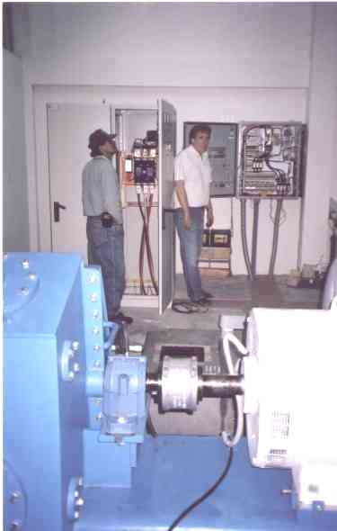
Photo shows pelton turbine (blue), generator, metering cabinet and
transformer for local power, and governor panel, (on right).
Load management
Here is the secret to how a 200 kW hydro plant can provide power to a total connected load of 300 kW or more. (This was more applicable to the project on Helena Creek. The current plan is to harness McCannel Creek which offers higher flows and a greater head. Load management will be less important in this situation.)
In addition to the governor controlling the precise speed of the generator and hence line frequency, load management diverts available power to useful loads arranged in a prioritized sequence. The load manager is always testing the amount of energy being dumped in the ballast load, and when there is sufficient excess, another prioritized load turns on. These can consist of water tanks, space heaters, display lighting, dryers, freezers, or any other load that can be shut off for a period of time with no ill effect.
Base loads such as lighting, pumps, outlets, kitchen appliances, sound equipment, computers, communications etc. are always connected. Should the available river flow be less that that needed to power the entire camp simultaneously, the load manager will shut off the lowest priority loads until a higher priority load or other base load shuts off. This arrangement will completely eliminate brown outs or total blackouts from overloading the turbine and causing the low frequency protection circuitry from shutting the system down. Load management has been installed on the diesel generators at Malibu to control a 30 kW electric water tank. Since it's installation there have not been any brown outs from overload on the system.
In a micro hydro plant it is desirable to run the turbine at the plant capacity, generating as much power as water flow permits. It costs no more to do this than to throttle back on the water. Remote telemetry sensors report on the water level at the river intake and will activate servo controls to throttle back on the water consumed should the water level begin to drop. In the case of McCannel Creek, a sensor in the lake will give advance indication of the water level changes allowing some planning in energy consumption if required.
Ballast load tank:
This is a water tank containing electric elements of up to 5000 watts capacity each. Excess power is shunted to these elements from the governor thereby "putting the brakes on" the generator. A small flow of water is continually flowing through the tank absorbing the excess energy. This excess power is often used as
a low priority source of heat for a pool or sauna. As lights are turned off in the buildings, the power
is immediately directed here to maintain the exact balance necessary for precise frequency control.
Governor loads can consist of space heaters. In the Malibu situation, heaters in dorms could be connected as available dump loads. In times of high base load demand, these heaters would not be energized.
However, as mentioned earlier, load management is not being planned for this development to the best of my knowledge.
Camp electrical load:
(See document by Mike Lewis.)
(Back to top)
Other studies:
There have been 6 separate studies done on this site by engineering firms.
1 Dependable Turbines, September 1991
2 Teracon Engineering. 1994
3 Leadcor Engineering, 1997
4 Leadcor Engineering, 2001
5 Tercon Engineering, 2002-3
6 JDP Hydro Group, 2002-3
This information is available upon request.
Mike Lewis has completed a major document entitled 'Prospects for Hydro Power Generation at the Malibu Club'. This document is available for study by interested parties.
|
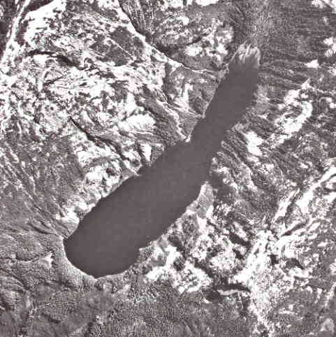 Air photo showing all of McCannel Lake. It is over two kilometers long, and on average, half a km wide. The lake outlet is visible on the lower left side of the photo.
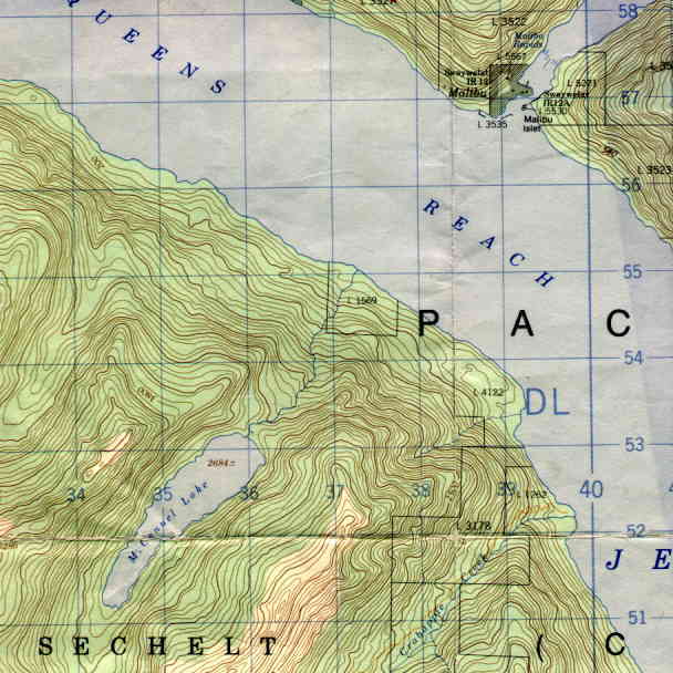 1 to 50,000 scale map showing the area of McCannel Lake, Creek , Jervis Inlet and Malibu
Camp. The blue squares are 1 km reference UTM lines.
1 to 50,000 scale map showing the area of McCannel Lake, Creek , Jervis Inlet and Malibu
Camp. The blue squares are 1 km reference UTM lines.